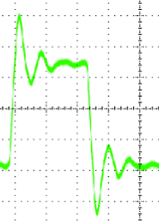
A Digital Pulse With Ringing
The test engineer was puzzled. He thought he had provided the correct commands to the programmable counter, but the results he was getting back from it were all wrong. To be within the test specifications, he should have been measuring a pulse-width around 500ms. Instead, he was getting a pulse-width of less than 10 nanoseconds. His first thought was that there must be a bug in the test script that was sending the commands to the counter. So, he manually programmed the counter from the front panel of the device. This didn’t help. He was still getting those short pulse-widths. Next he tried manually measuring the pulse-width using a digital storage scope. “That’s strange” he thought. It looks like the pulse width is 500 ms. He adjusted the time scale on the storage scope to 10 nanoseconds per division, and observed the rising edge of the pulse. There it was. The pulse was ringing on the rising edge. Ringing is the process where a signal that is transitioning from a low to a high state or from a high to a low state oscillates back and forth before settling on the final value. When viewed with an oscilloscope, this signal looks like the step response of a filter that causes oscillations until the oscillations are damped out. The recently graduated engineer didn’t know what was causing the ringing, since he had not included inductors, capacitors or resistors in the circuit that connected the device under test to the programmable counter. Still, he figured he could get rid of those oscillations by including a low pass filter before the input to counter. Another solution that he found easier was to program the counter to ignore any falling edges that occurred within the first 20 nanoseconds of the pulse. Years later, with a bit more experience, he realized what he had not realized then. He had failed to include a terminating resistor matching the impedance of his 50 ohm coaxial transmission line. If he had done this, the reflections that occurred at the point where the impedances were mismatched would have been made insignificant, and programmable counter would have measured 500ms from the beginning. Many times later when facing problems, the test engineer would think of this and muse “Perhaps the problem is I don’t know what I don’t know. Now, how do I solve that problem?”
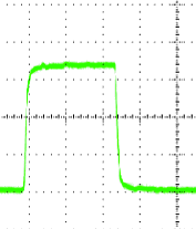
A Digital Pulse Without Ringing
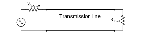
Transmission Line Including a Terminating Impedance
Here’s a nice technical discussion on terminating digital lines…
http://www.ni.com/white-paper/3854/en/
Here’s a nice technical discussion on calculating the impedance of a transmission lines…
http://www.allaboutcircuits.com/vol_2/chpt_14/3.html
Copyright 2013 All Rights Reserved NetChime Research LLC