Category Archives: Analog Design

Is a Smart Toilet in Your Future?

HAL smart toilet

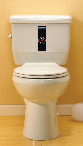
Is a smart toilet in your future?

When personal computers first appeared to on the market, there weren’t many people asking whether cars would have embedded computers. Today, a luxury sedan has somewhere around 60 embedded computers.  Yes, the Internet of Things is expanding, and that means we’ll be seeing more and more smart devices. Devices like these will also be communicating with each other so that they may work together to bring us more advanced information age benefits.

So, will toilets eventually have embedded processors?   Why change a good thing?  Why add a processor that will need software updates?  Why add electric power to a convenience that can function just fine without electric power?  These are very reasonable questions, and here are 5 possible answers.

1)   A smart toilet can include an automatic flush function.   A flushed toilet is always more presentable that an un-flushed one.  So, having an automatic flush function ensures that toilets are presented in the best possible light.  Self-flushing toilets already exist and can be found in public restrooms.  Assuming this functionality becomes popular in the home, the power needed for other smart functions will be available.

2)   A smart toilet can measure usage patterns.  By measuring how long someone is taking on the toilet, the smart toilet could remind the user to avoid taking too much time.  This could be done with and audible alert or more discretely by sending a text message to the user’s smart phone, reminding the user of the possible health consequences of prolonged toilet use.  To send this information by text messages, the smart toilet would need to identify the user.

3)   A smart toilet can measure a user’s regularity.  Once the smart toilet can identify the user, the smart toilet can also measure the regularity of the user, reporting trends and suggesting possible dietary changes to improve regularity (e.g. drink more fluids, eat more fiber, etc.).  In order to perform this function properly, the smart toilet might also need to communicate with other toilets.

4)   Similarly, a smart toilet could measure urinary frequency.  For male users, this function could be useful for detecting enlargement of the prostate.

5)   A smart toilet can also measure other healthcare information.   When traditional toilets are flushed, useful healthcare information is lost.  With more advanced sensors, a smart toilet can detect abnormal amounts of blood, or biochemical changes in the waste.   This can be helpful in the early detection of cancer.

Of course, there will probably be resistance to the idea of smart toilets. Some, perhaps most, people won’t like the idea of toilets recording their bathroom habits or having access to their healthcare information. Still, there are some practical and, perhaps, life saving benefits to be gained.   Consequently, when Smart Toilets start appearing, the manufacturers will need to assure their customers that these devices are secure and that their personal healthcare information will be kept private.   If buyers are convinced, smart toilets might eventually become more popular than the dumb toilets on the market today, and that’s an enormous market.

A smart toilet that’s already on the market…
http://singularityhub.com/2009/05/12/smart-toilets-doctors-in-your-bathroom/

Video of a smart toilet getting hacked…
http://www.forbes.com/sites/kashmirhill/2013/08/15/heres-what-it-looks-like-when-a-smart-toilet-gets-hacked-video/

Meanderings on Dancing, Dogs, Robotics and Artificial Intelligence

graceful robotics requires AI

Dancing Robots

To see dancing robots…   http://www.youtube.com/watch?v=4t1NWH6G1f0

After watching a dancer express herself so beautifully, conveying sensitivity, emotion and creativity, one can’t help but notice how far robotics has to go.  Sure… the robotic Atlas from Boston Dynamics is amazing, but it will probably be a long time before people will pass on the real thing to watch robots dance for pure aesthetics.  Similarly, when one considers the skill with which Fido can jump into the air and catch a ball, the dog certainly puts the latest robotic marvel in its place.

Still, the idea of graceful robots may not seem that far fetched.   The senses of joint position, position in space, space and time and gravity in humans are impressive, but machines can sense these things.   The skeletal/muscular capabilities of our bodies are also impressive, but, again, machines might generate similar motions.   The big difference is what is happening in the brain.

Imagine that we built a robot in a humanoid form, and that we gave each part a computer.  For example, the head had a computer in it; the left forearm had a computer in it, and so on.  Each of these computers would be responsible for controlling the artificial muscles and monitoring the sensors contained within that body part.    This is possible, and it has already been done.  Naturally, in such a configuration, to achieve coordinated motion of the whole, there would need to be a great deal of communications going on between the various computer/body parts.  This seems like it should be possible, since we can transmit vast amounts of data quite quickly around such a machine using fiber optic technology.   If each computer had capabilities like that of an iPhone, it might make great use of those accelerometers, always knowing which direction is down, knowing where it is and how it is being accelerated.  Add the high capacity communications, and perhaps each body part could know where it is and how it is moving relative to the inertial frame and to the other body parts.

To get to a graceful expression, however, it seems a few things are still needed…

the algorithms that are going to allow all those computers communicate with one another,
the instincts,
the desire,
the ability to set goals,
the ability to learn from mistakes,
the instructor’s training,
the practice,
the self-discipline,
the dream,
the passion,
the inspired music and choreography,
the feelings,
and finally, the encouraging applause from an appreciative audience who sees greatness in the performance.

or, in the case of the dog, a master’s pat on the head and piece of bacon.

Happy New Year!

Creepy yet graceful

Creepy Robot Spider

To see robotic spider move naturally…

http://www.youtube.com/watch?v=HfiHOpv6HtI

Removing Oscillations From The Rising and Falling Edges

Improperly terminated digital transmission lines will result in ringing

A Digital Pulse With Ringing

The test engineer was puzzled.  He thought he had provided the correct commands to the programmable counter, but the results he was getting back from it were all wrong.  To be within the test specifications, he should have been measuring a pulse-width around 500ms.  Instead, he was getting a pulse-width of less than 10 nanoseconds.  His first thought was that there must be a bug in the test script that was sending the commands to the counter.  So, he manually programmed the counter from the front panel of the device.  This didn’t help.  He was still getting those short pulse-widths.  Next he tried manually measuring the pulse-width using a digital storage scope.   “That’s strange” he thought.  It looks like the pulse width is 500 ms.    He adjusted the time scale on the storage scope to 10 nanoseconds per division, and observed the rising edge of the pulse.  There it was.  The pulse was ringing on the rising edge.  Ringing is the process where a signal that is transitioning from a low to a high state or from a high to a low state oscillates back and forth before settling on the final value.  When viewed with an oscilloscope, this signal looks like the step response of a filter that causes oscillations until the oscillations are damped out.  The recently graduated engineer didn’t know what was causing the ringing, since he had not included inductors, capacitors or resistors in the circuit that connected the device under test to the programmable counter.  Still, he figured he could get rid of those oscillations by including a low pass filter before the input to counter.   Another solution that he found easier was to program the counter to ignore any falling edges that occurred within the first 20 nanoseconds of the pulse.  Years later, with a bit more experience, he realized what he had not realized then.  He had failed to include a terminating resistor matching the impedance of his 50 ohm coaxial transmission line.  If he had done this, the reflections that occurred at the point where the impedances were mismatched would have been made insignificant, and programmable counter would have measured 500ms from the beginning.  Many times later when facing problems, the test engineer would think of this and muse “Perhaps the problem is I don’t know what I don’t know.  Now, how do I solve that problem?”

By adding a terminating resistor to the transmission line, the oscillations can be removed.

A Digital Pulse Without Ringing

This schematic shows a terminating resistor at the receiving end of the connection.

Transmission Line Including a Terminating Impedance

Here’s a nice technical discussion on terminating digital lines…

http://www.ni.com/white-paper/3854/en/

Here’s a nice technical discussion on calculating the impedance of a transmission lines…

http://www.allaboutcircuits.com/vol_2/chpt_14/3.html

Copyright 2013 All Rights Reserved NetChime Research LLC


Egad… Electromagnetic Interference is Emanating From the Prototype! (Part 1)

The electronics test engineer was the first to enter the lab that morning.   He turned on the radio and thought to himself  “That’s the third time I’ve heard that song today, and it’s so monotonous.”  It was time for a new station.  He turned the tuning knob and soon realized he was scanning the AM band.  “Why do the lab techs always insist on listening to AM stations?”  He switched the radio to the FM band and was soon listening to his favorite golden oldies station.  OK, it was time to get to work.

He applied power to the unit under test and a horrible buzzing sound filled the room.    It was coming from the radio.    He tried other FM stations on the radio.  Each one was accompanied by the buzzing sound.  “Oh…now I understand,” he thought.  The prototype has been generating electromagnetic interference.  That interference has been garbling the music on the FM stations.  The lab techs were probably adapting to this by only listening to the AM stations.

To test his theory, he switched the radio back to the AM band, trying various stations.  Each AM station came through loud and clear.  The electronics test engineer had a problem, because his company would not be able to sell a device that interfered with FM broadcasts.  He knew the prototype would eventually be sent to a special testing lab for an FCC certification.  The electromagnetic compatibility (EMC) test technicians there would also detect the interference.  He hoped he would be able to find the source of the problem and fix it before schedules and budgets were negatively impacted.

To be continued in “Egad… Electronic Interference is Emanating From the Prototype!   (Part 2)”

Egad… Electronic Interference is Emanating From the Prototype! (Part 2)

Continued from “Egad… Electronic Interference is Emanating From the Prototype!   (Part 1)”

He was reminded of his childhood, driving through the desert with his father, listening to music.  They had crossed over a river by driving over (actually by driving through) a truss bridge.  The radio went dead.  “What happened to the music Dad?” he asked.  His father, who had studied electronics in the Navy, said “Well son, this bridge is acting like a Faraday cage.  The metal is shielding us from the radio waves coming from the AM radio station. “

radio wave are shielded by the Faraday cage.

The truss bridge acts like a Faraday cage

“Why can’t the radio waves get through the holes in the cage?” he had asked.

“You can’t see them, but radio waves have a size called a wavelength and a strength called an amplitude.  These radio waves are too big and not strong enough to get very far through the holes.  If we switch to an FM station, we’ll be receiving radio waves with a shorter wavelength.  These wave are small enough to get through the holes, and we’ll hear the music again.”  The old man flipped the AM/FM band selector on the radio to FM, turned the tuning knob and, sure enough, there was music again.

Remembering this, the electronics test engineer realized that a metal lid had been removed from the prototype to replace some read only memory (ROM) components.  He selected the FM setting on the radio, and the buzzing returned. He found the lid, bolted it to the prototype, and the buzzing sound stopped.  There really wasn’t a problem after all.  The necessary shielding was in the design, and it had been removed during the ROM replacement.  The electronic test engineer was thankful for his discovery.  He had one less problem to worry about.   He was also thankful for the nice memory of driving through the desert and being with his father.

Click here to see an interesting presentation on EMC.

Including Test Points in Prototypes

Easy to use test point designed into circuit board

Circuit board with test point

A team of manufacturing test engineers was puzzled.  The spacecraft circuit board was failing tests, and not just a few tests.  It was failing all of the tests.  Spacecraft circuit boards aren’t inexpensive items, so a team of engineers went to work to determine exactly what had gone wrong.  To figure it out, they had to saw open integrated circuits and take microscopic photographs of the semiconductors. On the first of these, they noticed a path burned between the power input pin, Vcc, and the ground pin, Gnd.  Each subsequent chip examined provided the same evidence.  It appeared that someone or something had misapplied power to the unit under test.    At first, everyone was confused as to how this could have happened.  After all, the power supply cable that connected to the circuit board was keyed and was only capable of providing the correct input voltage.  Later, however, the problem was identified.  The technicians weren’t using this cable.  Instead, they were applying power to the circuit board though some test points in the test jig.   These test points were included for making measurements of the voltage applied to the circuit board.  After many tests, it seems someone had mistakenly connected the positive lead of the power supply to the ground test point, and the negative lead to the Vcc test point.  That was all that was necessary to destroy the circuit board and throw the schedule off by a month.


Insulated test points can help prevent accidental short circuits during testing

Test points with insulators

Normally, including a generous number of test points on circuit boards and on test jigs is a great idea.  This is particularly true for prototypes where at least some troubleshooting should be expected.  This makes it much easier for a lab technician to make measurements, and this saves time.   Of course, in many cases, it is also important to include current limiting resistors.  This will help prevent the sort of consequences described above and can also be important for the safety of you test crew.

This design does not include test current limiting resistors.  This can cause problems.

Without current limiting resistors

Including current limiting resistor with your test points can help avoid problems.

Battery test points with current limiting resistors

With current limiting resistors

copyright 2013 NetChime Research LLC,  All rights reserved.


Using the Arduino to Add Analog Inputs to Your Prototype

There is a small company who developed a very cool device with an embedded processor.   To speed their prototype development effort, the company used a commercial-off-the-shelf (COTS) processor board.   This processor came with an open source operating system and some convenient interfaces, which allowed the designers to use the same processor for software development.   They made a nice looking enclosure for the device, found a compatible power supply, and quickly assembled something they would be proud to show a potential investor.

Unfortunately, after all that hard work, they realized they needed an analog input that they didn’t have.  It was for a volume control knob, which they felt would greatly improve the user experience.  At the time they were shopping for the processor board, they didn’t realize they needed that analog input.  Consequently, although being very careful to select something powerful and flexible, they picked something that fell short in this small, but important area.

Here’s how they solved the problem.  They added another processor, one that you don’t see often in commercial prototypes.   They added an Arduino Duemilanove.  Yes, the Arduino is one of the processors you see advertised in electronic hobbyist
e-zines.  Hobbyists love these devices, because they are inexpensive and easy to use.   Well… guess what?  Professionals also love devices that are inexpensive and easy to use.

They could use Arduino, because the original COTS processor had an extra USB interface.  At first, the idea of using an Arduino to provide the analog interface received resistance.   They were told, “You don’t understand the complexities of the USB protocol stack.”  And “This approach will take too long to code up. “

So they took a little time to investigate the approach.  This is what they found.  It was easy, so easy, in fact, that they were able to demonstrate the solution in less than 4 hours.   They connected a little potentiometer up to the Arduino with three wires.  That was that easy.  They found a pre-written script for sampling an analog input and transmitting those samples over the Arduino’s USB interface.   And that was easy.  They downloaded and installed the Arduino development software and then loaded the Arduino sampling script into the Arduino.  Next, they connected the Arduino to the COTS processor.  They had to write a little shell script to run on the open source operating system to see their results, but that was easy too.    This was just another serial device as far as the operating system was concerned.

What was really nice was that the Arduino got its power through the USB interface.  So, it was not necessary to provide another voltage source to power the Arduino.

Also, since the Arduino is small, they could fit it inside the existing enclosure.

In the field of rapid prototype development, you need to be creative, and you need to think out of the box.  But most of all, you need to be quick.   If you’re taking too long to implement the next wiz bang device, you might just be allowing your competition to beat you to the market.  That can mean missing a grand opportunity.  The company realized this, and they did what needed to be done.

After the accomplishment, the team jokingly claimed “we have just constructed the world’s most expensive volume control knob,” but they all knew the truth.   When it comes to prototype development, time is money, and this was the least expensive way to achieve the desired result and still make their schedule.

copyright 2013 NetChime Research, LLC,  All rights reserved.

http://www.netchime.com