Category Archives: Digital Design

“FIPS 140 Made Easy” Part 3

Continued from FIPS 140 Made Easy part 2…

“What about FIPS 140-3?”

“You should probably check the FIPS 140-3 standard as well.  Presently, it’s in a draft form.  So, it could change.  Still, it’s possible FIPS 140-3 could become the new standard before you’re through with your current certification effort.  Knowing what’s in it shouldn’t hurt you.  Here’s the link for you…”

http://csrc.nist.gov/publications/PubsDrafts.html#FIPS-140–3

“Anything else?” asked the product manager.

“Yes.  The next time you design a crypto device, consider whether you need a FIPS 140 certification and what level of certification you might need during the requirements definition phase.  It is usually easier to get your crypto design certified when it is designed to meet the security requirements from the outset.  Modifying an existing design to meet the same requirements, after the fact, can be quite difficult. “

The information security engineer got the job, but it was a short contract.  Soon, the product manager began to realize how important that last piece of advice was, and the company decided it didn’t have the time or the money to seize that big government business opportunity.

The End

Including Test Points in Prototypes

Easy to use test point designed into circuit board

Circuit board with test point

A team of manufacturing test engineers was puzzled.  The spacecraft circuit board was failing tests, and not just a few tests.  It was failing all of the tests.  Spacecraft circuit boards aren’t inexpensive items, so a team of engineers went to work to determine exactly what had gone wrong.  To figure it out, they had to saw open integrated circuits and take microscopic photographs of the semiconductors. On the first of these, they noticed a path burned between the power input pin, Vcc, and the ground pin, Gnd.  Each subsequent chip examined provided the same evidence.  It appeared that someone or something had misapplied power to the unit under test.    At first, everyone was confused as to how this could have happened.  After all, the power supply cable that connected to the circuit board was keyed and was only capable of providing the correct input voltage.  Later, however, the problem was identified.  The technicians weren’t using this cable.  Instead, they were applying power to the circuit board though some test points in the test jig.   These test points were included for making measurements of the voltage applied to the circuit board.  After many tests, it seems someone had mistakenly connected the positive lead of the power supply to the ground test point, and the negative lead to the Vcc test point.  That was all that was necessary to destroy the circuit board and throw the schedule off by a month.


Insulated test points can help prevent accidental short circuits during testing

Test points with insulators

Normally, including a generous number of test points on circuit boards and on test jigs is a great idea.  This is particularly true for prototypes where at least some troubleshooting should be expected.  This makes it much easier for a lab technician to make measurements, and this saves time.   Of course, in many cases, it is also important to include current limiting resistors.  This will help prevent the sort of consequences described above and can also be important for the safety of you test crew.

This design does not include test current limiting resistors.  This can cause problems.

Without current limiting resistors

Including current limiting resistor with your test points can help avoid problems.

Battery test points with current limiting resistors

With current limiting resistors

copyright 2013 NetChime Research LLC,  All rights reserved.


Using the Arduino to Add Analog Inputs to Your Prototype

There is a small company who developed a very cool device with an embedded processor.   To speed their prototype development effort, the company used a commercial-off-the-shelf (COTS) processor board.   This processor came with an open source operating system and some convenient interfaces, which allowed the designers to use the same processor for software development.   They made a nice looking enclosure for the device, found a compatible power supply, and quickly assembled something they would be proud to show a potential investor.

Unfortunately, after all that hard work, they realized they needed an analog input that they didn’t have.  It was for a volume control knob, which they felt would greatly improve the user experience.  At the time they were shopping for the processor board, they didn’t realize they needed that analog input.  Consequently, although being very careful to select something powerful and flexible, they picked something that fell short in this small, but important area.

Here’s how they solved the problem.  They added another processor, one that you don’t see often in commercial prototypes.   They added an Arduino Duemilanove.  Yes, the Arduino is one of the processors you see advertised in electronic hobbyist
e-zines.  Hobbyists love these devices, because they are inexpensive and easy to use.   Well… guess what?  Professionals also love devices that are inexpensive and easy to use.

They could use Arduino, because the original COTS processor had an extra USB interface.  At first, the idea of using an Arduino to provide the analog interface received resistance.   They were told, “You don’t understand the complexities of the USB protocol stack.”  And “This approach will take too long to code up. “

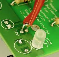
So they took a little time to investigate the approach.  This is what they found.  It was easy, so easy, in fact, that they were able to demonstrate the solution in less than 4 hours.   They connected a little potentiometer up to the Arduino with three wires.  That was that easy.  They found a pre-written script for sampling an analog input and transmitting those samples over the Arduino’s USB interface.   And that was easy.  They downloaded and installed the Arduino development software and then loaded the Arduino sampling script into the Arduino.  Next, they connected the Arduino to the COTS processor.  They had to write a little shell script to run on the open source operating system to see their results, but that was easy too.    This was just another serial device as far as the operating system was concerned.

What was really nice was that the Arduino got its power through the USB interface.  So, it was not necessary to provide another voltage source to power the Arduino.

Also, since the Arduino is small, they could fit it inside the existing enclosure.

In the field of rapid prototype development, you need to be creative, and you need to think out of the box.  But most of all, you need to be quick.   If you’re taking too long to implement the next wiz bang device, you might just be allowing your competition to beat you to the market.  That can mean missing a grand opportunity.  The company realized this, and they did what needed to be done.

After the accomplishment, the team jokingly claimed “we have just constructed the world’s most expensive volume control knob,” but they all knew the truth.   When it comes to prototype development, time is money, and this was the least expensive way to achieve the desired result and still make their schedule.

copyright 2013 NetChime Research, LLC,  All rights reserved.

http://www.netchime.com